")
")
")
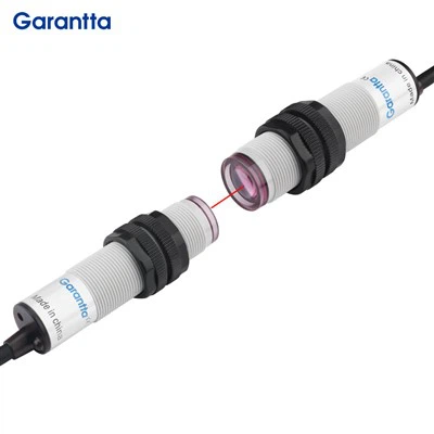
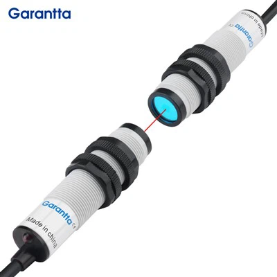
Through beam photoelectric sensors are controlled by converting changes in light intensity into changes in electrical signals. In general, photoelectric sensors consist of three parts, which are: transmitter, receiver, and detection circuit. The transmitter aims at the target to emit a beam of light, which generally comes from semiconductor light sources, light-emitting diodes (LEDs), laser diodes, and infrared-emitting diodes. The beam emits continuously or changes the pulse width. The receiver consists of a photodiode, a phototransistor, and a photocell. In front of the receiver, optical components such as lenses and apertures are installed. Behind it is the detection circuit, which can filter out effective signals and apply them.
Main features
Built-in amplifier, resistant to sunlight interference
Through Beam Photoelectric Sensor (red light source, detection distance up to 10m) products are equipped with filters to prevent mutua! interference and can be used to resist sunlight;
Diffuse reflection products have a sensing distance of 300mm, built-in high-performance chips, and stable performance;
Improved the consistency between the optical axis and the mechanical axis
The deviation between the optical axis and the mechanical axis is controlled within +2.5. lt only needs to be installed in conjunction with the mechanical axis to achieve high-precision alignment with the optical axis. Through-beam and mirror-reflective types achieve longer detection distances.
Even if the wiring is wrong, the sensor can be protected
Equipped with output reverse polarity protection function (add reverse polarity protection diodes to the output line)

Wire Menthod of Through Beam Photoelectric Sensor
A reflective photoelectric switch is a commonly used sensor for detecting the presence or position of an object. The following is a wiring tutorial for a pair of photoelectric switches:
Determine input and output: Firstly, you need to determine the input and output of the photoelectric switch. Usually, this type of switch has an input terminal (usually a red or brown wire) and an output terminal (usually a black or blue wire).
Connect input: Connect the input terminal to the power supply. This is usually a DC power supply, such as 5V or 12V. Ensure that the positive pole of the power supply is connected to the positive pole of the input terminal, and the negative pole is connected to the negative pole of the input terminal.
Connect output: Connect the output terminal to the device you want to control. This could be a motor, a light, a sound device, etc. Ensure that the positive pole of the device is connected to the positive pole of the output terminal, and the negative pole is connected to the negative pole of the output terminal.
Test: Place the object within the detection range of the photoelectric switch with the power on. If everything is normal, you should be able to see your device activated. If not, you may need to check if your wiring is correct or if your device requires specific voltage or current.
Attention: During the wiring process, ensure that the power is turned off to prevent electric shock. If you are unsure how to connect the wires, it is best to seek the help of a professional.
Application of through beam photoelectric sensor in industry
In industry, photoelectric detection technology is commonly used in the following areas:
- Quality inspection: Photoelectric sensors can detect the physical properties such as size, shape, and surface characteristics of various materials and products. Their applications include size sorting, channel width detection, object classification, etc. Especially for small parts or parts with special shapes, using photoelectric sensors for precise measurement is very effective.
- Motion detection: Photoelectric sensors can also detect information such as the position, motion status, and return accuracy of robots and other automated equipment. This type of technology is applied in logistics robots, automatic doors, intelligent pallets, and other occasions, coordinating the real-time update and transmission of signals from various components through optical power feedback, ensuring the normal operation of the equipment and having self-recovery ability.
- Safety protection: Photoelectric detection technology can control the smooth start and stop of moving components, and can achieve safety protection for operators in the production line or special hazardous areas in the workshop by quickly cutting off operation modules and forced shutdown mechanisms.
- Automatic control: Photoelectric detection technology can be used to control the sequence, speed, and quality of various links on automatic assembly lines. Factories pay special attention to managing different machine tool devices and material transportation through signal sensitive fast switching optical fibers and digital sensors in longer production processes.
▲ Automatic doors and security systems: Reflective photoelectric sensors are used to monitor personnel entering and exiting areas such as doorways and corridors, in order to automatically open or close doors, providing safety protection and convenience.
▲Line control and limit detection: Contrasting photoelectric sensors can be used to detect the position, direction, and driving speed of objects, commonly used for limit detection, position judgment, and trajectory tracking of mechanical equipment.
▲Conveyor line and assembly line control: Reflective photoelectric sensors can be used to detect the arrival, departure, and stopping status of objects, achieving material conveying and process control on automated production lines.
▲Product counting and sorting: Contrasting photoelectric sensors can be used to detect and count products passing through conveyor belts, and sort and classify them according to preset conditions.
▲Printing and packaging industry: Reflective photoelectric sensors can be used to detect the position, defects, positioning, etc. of paper or products during transportation, improving the quality of printing and packaging.
Precautions for using Through Beam Photoelectric Sensor
1 - Places where photoelectric sensors should be avoided for use
1. Places with a lot of dust;
2. Places with a high concentration of corrosive gases;
3. Places where water, oil, and chemicals may directly splash;
4. Outdoor or places with strong direct sunlight without shading measures. Places where the environmental temperature changes beyond the specified range of the product; Places with high vibration and impact without taking shock absorption measures.
2 - Precautions for using photoelectric sensors
1. Avoid strong light sources
Through Beam Photoelectric Sensor can generally work stably in high environmental illumination. However, avoid aligning the sensor's optical axis directly with strong light sources such as sunlight and incandescent bulbs. When the angle between the optical axis of the sensor (receiver) and the strong light source cannot be changed, a light shielding plate or a long light-shielding tube can be installed around the top of the sensor.
2. Prevent mutual interference
Optoelectronic sensors usually have the function of automatically preventing mutual interference, so there is no need to worry about mutual interference. However, when several groups of infrared photoelectric sensors are installed in parallel and close proximity, adjacent groups and mutual interference should be prevented. The most effective way to prevent this interference is to cross-set the projector and receiver, and when there are more than two groups, the group spacing should be widened. Of course, using models with different frequencies is also a good approach.
3 - Impact of mirror angle
When the object being tested has a glossy surface or encounters a smooth metal surface, the reflectivity is generally high and has a mirror-like effect. At this time, the projector and the object being tested should be installed at an angle of 10-20 ° to prevent the optical axis from being perpendicular to the object being tested and to prevent misoperation.
4 - Eliminate the influence of background objects
When using a reflective diffusion type projector or receiver, sometimes the photoelectric sensor may not be able to detect stably due to the proximity of the detected object to the background, or because the background is a smooth object with high reflectivity. Therefore, distance limited projectors and receivers can be used instead, or methods such as keeping away from the background, removing the background, painting the background black without light, or trying to make the background rough and dark can be used to eliminate it.
Three detecting method of Photoelectric Optic Sensor
Regarding the types of photoelectric sensors: There are many different types of photoelectric sensors, but in reality, there are only four basic technologies: mirror reflection, diffuse reflection, background suppression, and through beam photoelectric sensor
Comparison of advantages and disadvantages of through beam photoelectric sensor:
Advantages: The most accurate among the four types of photoelectric sensors, with the longest sensing range and extremely high reliability.
Disadvantage: It requires installation in two positions of the application system: transmitter and receiver, with high cost. Both transmitter and receiver must be purchased at the same time.
Comparison of advantages and disadvantages of mirror reflection photoelectric sensors:
Advantages: Lower cost compared to conventional photoelectric sensors, lower accuracy than conventional sensors, wider sensing range than diffuse sensors, and higher reliability
Disadvantage: It needs to be installed in two positions of the application system: transmitter and transmitter. The cost is slightly higher than diffuse reflection, and the sensing range is smaller than that of opposite reflection.
Comparison of advantages and disadvantages of diffuse reflection photoelectric sensors:
Advantages: Only installed at one point of the application, with lower cost compared to reflective and mirror reflective systems
Disadvantage: Not as accurate as reflective or mirror reflection, may require more setup time
Comparison of advantages and disadvantages of background suppression photoelectric sensors:
Advantages: Can effectively work against reflective backgrounds
Disadvantages: Higher cost compared to diffuse reflection, mirror reflection, or reflective types, requiring the longest debugging and setup time


FAQ
About Garantta
Garantta Sensor Technology (Garantta) is a high-tech enterprise specializing in sensor products. The main products include the photoelectric sensor series, fiber optic sensor series, temperature sensor series, proximity sensor series, safety light curtain sensor series, measurement sensor series, flow measurement sensor series, pressure sensor series, liquid level sensor, and composite sensor (MEMS). Products are widely used in automation equipment, medical equipment, 3C digital products, automobiles, home appliances, and other fields. From core accessories, to product strategy, and supplier management, we insist on high-quality workmanship and pursue the ultimate quality. We are not only committed to meeting the needs of many customers in the manufacturing and R&D industries but are also committed to future development and providing customers with more long-term improvements and solutions. In addition to providing excellent products and solutions, we also provide customers with richer industry knowledge and more professional technical solutions to help customers achieve higher achievements.
Company Vision
Let sensing technology benefit manufacturing and life
Company Mission
Corporate mission: Provide customers with high-quality and reliable sensor products and technical solutions to help customers achieve higher achievements

1000+
Sensor Series
10000+
Customers
200+
Agent
2000+
Projects Completed
Finding our office website in Google, check the product link you need, and contact us, send us your sensor requirements solution
Our address
Room 1007-1008, 10th Floor, Building 7, Hengda Fashion Valley, Dalang Street, Longhua New District, Shenzhen
Phone Number
+ 86 13530821762
info@garantta.com

FAQ

01.How we control the through beam photoelectric sensor quality?
02.Can we accept samples customized?
03.What about the production capacity?
04.OEM and ODM are available?
05.Will the delivery time be long for a big order?
06.What is our through beam photoelectric sensor warranty service?
Hot Tags: through beam photoelectric sensor, China through beam photoelectric sensor manufacturers, suppliers, factory, photocell beam sensor, fiber optic motion sensor, flush and non flush proximity sensor, laser photoelectric switch, long distance through beam photoeletric sensor, Photo beam sensors
| Technical Parameter | ||||||||||||
| Model | Detection method | Detection distance | Wiring method | Control output | Light source | Reaction time | Display indicator | Control output | Power supply | Working environment brightness | Power consumption | Vibration resistance |
| GPS-T61 | Through-beam type | 50mm-15000mm | NPN | 1 output port, equipped with short circuit protection and automatic anti-interference function | Red light 650NM, laser diode | Within 1MS | Operation indicator: Green LED indicates power indicator, red LED indicates output | NPN/PNP open collector 24V, maximum 100mA (main component only) Residual voltage: 1V | Between 12 and 24VDC ±10%, floating ratio (P-P): 10% maximum Level 2 | Incandescent: Maximum: 20,000lux, Daylight: Maximum: 30,000lux | Standard mode: Max 300mW Maximum voltage: 24V |
10 to 55Hz, dual amplitude: 1.5mm, X, Y, Z axes are 2 hours each |
| GPS-T81 | PNP | |||||||||||
| GPS-D61 | Diffuse reflection type | 5mm-100mm | NPN | Red light 635NM, 4-element light-emitting diode body | ||||||||
| GPS-D81 | PNP | |||||||||||
| GPS-D62 | 20mm-400mm | NPN | ||||||||||
| GPS-D82 | PNP | |||||||||||
| GPS-R61 | Retro-reflective type | 30mm-4000mm | NPN | Laser red light 650NM | ||||||||
| GPS-R81 | PNP | |||||||||||
| GPS-S61 | Background-suppression retroreflective type | 10mm-100mm(60mm Built-in background suppression) | NPN | Red light 635NM, 4-element light-emitting diode body | ||||||||
| GPS-S81 | PNP | |||||||||||
| GPS-S62 | 20-700mm(300mm Built-in background suppression) | NPN | ||||||||||
| GPS-S82 | PNP | |||||||||||
| GPS-B61 | Transparent bottle retroreflective | 20mm-4500mm | NPN | Red PIN POINT LED, 4-element light-emitting diode body | Operation indicator light: The green LED indicator light indicates the power indicator light, and the red LED indicates the output. During self-learning, the red light and the green light are used together as the self-learning status light. | |||||||
| GPS-B81 | PNP | |||||||||||