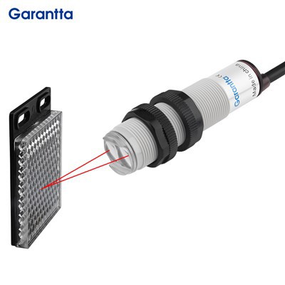
The Garantta GFO-EV11 Fiber Optic Sensor Amplifier is a cost-effective, general-purpose industrial sensor for detecting small objects and performing high-precision measurements. Its core working principle involves transmitting and receiving light through a fiber optic cable, with the fiber optic amplifier determining the presence or absence of an object based on changes in the received light intensity. This makes it ideal for detecting small objects or for use in harsh or confined spaces.
| Quantity | Unit price (GFO-EV11-N/GFO-EV11-P) |
| 1-50pcs | 15.71usd/pcs |
| 50-100pcs | 14.5usd/pcs |
| ≥100pcs | 13.57usd/pcs |
Technical Parameters
| Parameter Item | GFO-EV11-N / GFO-EV11-P Specification |
|---|---|
| Detection Principle | Light intensity judgment, auto sensitivity tracking function |
| Light Source | Red 4-element LED light source |
| Control Output Channel | Single output, built-in short-circuit & anti-interference circuit |
| Response Time | P0:25μs / P1:50μs / P2:100μs / P3:200μs / P4:800μs switchable |
| Output Mode | Light-on / Dark-on, button one-click switching |
| Display Indicator | Red running LED; dual 7-digit digital screen; green threshold indicator + red real-time value indicator (0~9999 range) |
| Delay Function | Off delay / On delay / Single trigger / Delayed single trigger; timing range 1ms~9999ms adjustable |
| Electrical Output | NPN/PNP open collector 24VDC, max load 100mA; extension unit max 20mA, residual voltage ≤1V |
| Power Supply | 12~24VDC ±10%, ripple peak-to-peak ≤10%, Class 2 power standard |
| Ambient Light Resistance | Incandescent light max 20,000lux; natural sunlight max 30,000lux |
| Power Consumption | Standard mode ≤300mW |
| Vibration Resistance | 10~55Hz, double amplitude 1.5mm, X/Y/Z axis continuous 2h test |
| Working Temperature | -10℃ ~ +55℃, no icing allowed |
| Model Classification | GFO-EV11-N (NPN normally open)GFO-EV11-P (PNP normally open) |
| Matching Fiber Type | Through-beam fiber / Diffuse reflection fiber (optional separately) |
| Minimum Detectable Object | 0.04mm tiny metal pins, micro electronic components |
| Certification Standard | CE, ROHS, industrial EMC EN IEC61000 series |
Advantages of Fiber Optic Sensor Amplifier
1. Ultra-small object detection capability Equipped with ultra-fine fiber probe, detection spot tiny enough to identify 0.04mm micro wires, electronic pins, tiny tablets, printing tiny marks, which ordinary photoelectric sensors cannot detect.
2. Adaptable to complex narrow & harsh environments Fiber probe thin and bendable, can be embedded inside robotic arms, narrow fixture gaps, small injection mold equipment. Glass fiber probe withstand high temperature up to 150°C, separate amplifier installed in cool area to avoid high-temperature damage to circuit board.
3. Super anti-interference, stable detection without false alarms Optical fiber transmission avoids electromagnetic interference from frequency converters, motors, welding equipment. Built-in ambient light filtering algorithm, resistant to strong sunlight, workshop strobe lights, no signal drift.
4. Easy installation & flexible layout Two installation modes (DIN rail mounting / screw fixed mounting), single-side through-beam two layout options, wiring simple, no complex auxiliary brackets required. Compatible with all mainstream PLC brands on the market.
5. Cost-effective & low maintenance Competitive factory direct price, tiered bulk discount policy; low failure rate, long service life, reduce equipment downtime and sensor replacement costs, improve overall production line operation efficiency.
Application of Fiber Optic Sensor Amplifier
Garantta GFO-EV11 fiber optic amplifier matched with fiber probes is widely applied in full industrial automation industries for object presence detection, counting, positioning, defect inspection:
- 3C electronics manufacturing: PCB pin detection, chip presence inspection, tiny plastic parts counting, electronic component assembly positioning
- Printing & packaging machinery: printing color mark detection, transparent film/glass bottle detection, packaging box in-place judgment, product counting
- Medical equipment: capsule/tablet counting, medical micro parts size inspection, disposable medical supplies positioning
- Rubber & plastic machinery: injection molding product ejection detection, small plastic burr defect inspection
- Intelligent logistics sorting: small parcel identification, high-speed conveyor goods counting
- Woodworking & textile machinery: fabric edge detection, small wood accessory positioning
- Automotive automation: micro wiring harness detection, auto small stamping parts inspection
- Household appliance production: micro hardware fitting detection, assembly missing part inspection


Fiber Optic Sensor Amplifier Troubleshooting Guide
Pre-Troubleshooting Preparation Work
Before troubleshooting GFO-EV11 fiber optic amplifier, complete the following preparations to ensure safe and efficient maintenance:
Document preparation: Prepare amplifier user manual, wiring schematic, parameter setting guide for reference of standard parameters and fault solutions
Tool preparation: Multimeter, alcohol cleaning cloth, screwdriver, spare fiber probe, replacement wiring cable
Safety operation specification: Cut off equipment total power supply before inspection, avoid live wiring operation to prevent electric shock and circuit burnout
Step-by-Step Troubleshooting Process
Step 1: Power supply inspection
Operation steps: Check whether the power line of the amplifier is loose, broken, or aging; check whether the switching power supply module outputs abnormally. Test method: Use multimeter DC voltage gear to measure input terminal voltage, confirm voltage stays within 12~24VDC normal range. Fault judgment: No display on digital screen = power supply damage / wiring open circuit; flickering screen = unstable power supply voltage.
Step 2: Indicator light & digital screen status judgment
Normal working state: Power red light steady on, digital screen displays stable light intensity value, output light lights up when detecting objects. Abnormal judgment:
All lights off: Power failure or internal main board burnout
Digital screen value always 0: Fiber probe blocked, fiber broken, emitter/receiver end dirty
Digital screen value fluctuates drastically: Ambient strong light interference, fiber loose joint, fiber bending excessively
Output light never lights up: Sensitivity setting too low, output mode mismatched, fiber type mismatch
Step 3: Fiber probe & optical path inspection
Operation steps: Take out fiber probe, wipe the lens end with alcohol cloth to remove oil, dust, plastic debris; check whether fiber has sharp bending, extrusion breakage. Test method: Block the fiber detection end with hand, observe whether digital screen value changes significantly. Solution: Dirty lens → clean; fiber broken → replace fiber probe; excessive bending → re-lay fiber with larger bending radius.
Step 4: Parameter setting calibration inspection
Operation steps: Check current sensitivity threshold, response speed, delay time, Light-on/Dark-on mode settings. Adjustment method: Press automatic tracking button to reset sensitivity; switch response speed to low speed for high-interference environments; switch output logic according to PLC signal demand.
Step 5: Environmental interference inspection
Inspection items: Whether there are strong sunlight, welding arc light, high-power frequency converter, motor near the detection position. Optimization scheme: Add light-shielding baffle for fiber probe; move amplifier main unit away from electromagnetic equipment; replace anti-high-light fiber model.
Step 6: Wiring & line inspection
Operation steps: Check M12 connector pins for oxidation, loose contact, wire core breakage. Test method: Multimeter continuity test for power line and output signal line. Solution: Oxidized joint wipe clean; broken wire replace wiring cable; loose connector re-lock.
Step 7: Internal circuit fault detection
If all above steps are checked and faults still exist, the amplifier internal main board chip or circuit is damaged. Treatment suggestion: Do not disassemble privately to avoid secondary damage; contact Garantta professional technical support for repair or replacement.
Troubleshooting Precautions
Regular daily inspection of amplifier and fiber probes to reduce sudden downtime faults
Conduct professional operation training for production line operators, master basic fault judgment and simple adjustment methods
Establish equipment fault record form, record each fault phenomenon, processing steps and results for later maintenance reference
Avoid dragging, hard bending fiber during daily use to extend fiber service life
Product Daily Maintenance Methods
Regularly inspect the lens surface of fiber probes for scratches, oil stains and dust; once lens scratch occurs, immediately replace the fiber probe to avoid detection failure
For production lines with heavy oil mist, wipe fiber lens and amplifier shell with alcohol-dampened clean towels every 3~7 days to remove oil dirt accumulation
Keep the installation environment around the amplifier clean, regularly sweep dust and plastic debris to prevent dust from entering the M12 wiring interface and causing poor contact
Check fiber wiring routing every month, fix loose fiber fixing clips, avoid long-term friction with mechanical moving parts leading to fiber breakage
For high-temperature workshop environments, regularly check amplifier heat dissipation, avoid stacking other equipment to block heat dissipation holes; install cooling fan if necessary
Complete maintenance can effectively extend the service life of fiber optic amplifiers, reduce replacement costs, and guarantee continuous stable operation of automated production lines
Garantta Sensor Customer Service
1. Diversified Payment Options: To accommodate the diverse transaction habits of our customers, Garantta Sensor supports multiple payment methods, including T/T (Telegraphic Transfer), PayPal, Western Union, Letter of Credit (L/C), and Trade Assurance, ensuring a smooth and convenient cooperation process.
2. Efficient and Reliable Delivery Cycle: Based on inventory status and order scheduling, we offer flexible delivery times. Standard Fiber Optic Sensor Amplifier are readily available and can be shipped within 5-7 days; customized products or bulk orders require a 25-40 day production and quality inspection cycle, balancing efficiency and reliability.
3. Personalized Sales Strategy: We serve end-users, equipment buyers, and distributors, and provide tiered pricing plans based on purchase volume, helping various customers optimize procurement costs and maximize value.
4. Comprehensive Quality Control System: Garantta Sensor implements company-wide quality control, from comprehensive testing of raw materials before warehousing to 100% testing of every fiber optic amplifier before shipment. Strict control at every stage significantly reduces the risk of defective products and ensures the stability and reliability of delivered products.
5. Commitment to Long-Term Mutual Benefit: We believe that the sustainable development of our company stems from creating real value for our customers – guaranteeing customer interests through high-quality products and competitive pricing. For long-term partners, Garantta will provide exclusive benefits, including: the most advantageous price discounts, priority production and delivery channels, fast and professional technical solution support, and special subsidies and collaborative services for participating in industry exhibitions.

FAQ
Q:In what scenarios are Fiber Optic Sensor Amplifier best suited for use?
A1: Fiber optic amplifiers are particularly suitable for the following three types of scenarios:
Space-constrained environments: When the detection point is located in narrow gaps, inside robotic arms, or in small devices where traditional sensors cannot be installed, the thin and flexible fiber optic head can easily reach the target.
Harsh environments: When the detection point is subject to high temperatures, oil, dust, or vibration, the durable fiber optic head (some models can withstand temperatures up to 150°C) can be placed there, while the amplifier body is installed in a distant, milder environment, protecting the core electronic components.
Detection of tiny objects: With its extremely small light spot, it can reliably detect objects such as miniature electronic components (capacitors, pins), tablets, fine wires, and precision markings, with a minimum detectable object diameter of up to 0.04 millimeters.
Q2: How to choose between through-beam fiber and diffuse reflection fiber for matching?
A: Two fiber types have different applicable conditions, select according to detected objects and installation space:
Through-beam fiber: Transmitter and receiver separated on two sides, detection stability extremely high, not affected by object color, surface reflectivity. Ideal for transparent objects (glass bottles, PET film) and high-reliability counting stations; need double-side alignment during installation.
Diffuse reflection fiber: Transmit & receive integrated in single probe, only single-side installation required, simple wiring. Detection effect affected by object color (dark color weak reflection); mainly used for opaque workpiece presence detection. Selection suggestion: Prioritize through-beam fiber for stable detection demand; choose diffuse reflection fiber when only single-side installation space is available, adjust sensitivity to balance detection stability.
Q3: Why does the Fiber Optic Sensor Amplifier output false trigger signal frequently? How to solve it?
A: Common causes & corresponding solutions:
Ambient strong light interference (sunlight, welding lamp): Add light shield at fiber probe, increase anti-high-light parameter threshold, or re-adjust installation position to avoid direct light irradiation.
Fiber lens covered with oil/dust: Wipe lens with alcohol cloth, clean workshop surrounding oil mist regularly.
Sensitivity set too high: Press auto-tracking button to re-calibrate sensitivity, reduce detection threshold appropriately.
Fiber over-bending or internal breakage: Replace fiber probe, rearrange wiring with larger bending radius.
Unstable power supply: Replace industrial regulated DC power supply to ensure voltage stable within 12~24VDC.
Hot Tags: fiber optic sensor amplifier, China fiber optic sensor amplifier manufacturers, suppliers, factory, fiber optic light detector, optical fiber sensor instruction, optical fiber coupler, optical fiber flow sensor, fiber optic sensor cost, optical fiber transducer
| Detection method | Light intensity (area detection available, automatic sensitive tracking function available) | ||
| Light source | Red, 4-element LED body | ||
| Control output | 1 output port, equipped with short circuit protection and automatic anti-interference function | ||
| Type | 1 output port, lead-out type | ||
| Reaction time | P0: 25μs P1: 50μs, P2: 100μs P3: 200μs, P4: 800μs | ||
| Output selection | LIGHT-ON/DARK-ON (button selection) | ||
| Display indicator | Operation indicator: red LED, dual digital monitor: dual 7-digit display, threshold (4-digit green LED body indicator) and current value (4-digit red LED body indicator) light up together. Current value range: 0-9999 | ||
| Delay function | Off delay timer/on delay timer/single timer/on delay single timer are selectable. Meter display in duration selectable: 1ms to 9999ms | ||
| Control output | NPN/PNP open collector 24V, maximum 100mA (main unit only) maximum 20mA (when extension unit is connected, residual voltage: 1V | ||
| Power supply | Between 12 and 24VDC ±10%, floating ratio (P-P): 10% maximum Class 2 | ||
| Working environment brightness | Incandescent: Maximum: 20,000lux, Daylight: Maximum: 30,000lux | ||
| Power consumption | Standard mode: Maximum 300MW; Maximum voltage: 24V | Standard mode: Maximum 300MW; Maximum voltage: 24V | |
| Vibration resistance | 10 to 55Hz, dual amplitude: 1.5mm, X, Y, Z axes are 2 hours each | ||
| Ambient temperature | -10 to +55℃, no freezing | ||
| Model | NPN NO | GFO-EV11-N | |
| PNP NO | GFO-EV11-P | ||